Circuit Symbol For Boost Converter
Circuit diagram of boost converter . Boost converter Ideal circuit of a boost converter
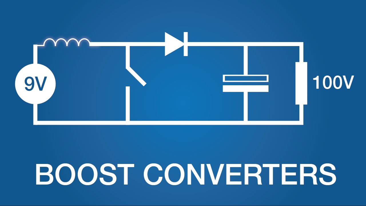
DC to DC Boost Converter Circuit (Part 5/9)
Dc to dc converter circuits using sg3524 [buck, boost designs How to build a dc-to-dc boost converter circuit Converter topological
Boost converter switch wikipedia state off pdf current electronics when configurations generator two time circuit depending simple power inductor wiki
Circuit diagram of boost converter [25].1 circuit diagram of boost converter. Circuit dc converter boost build inductor shown below breadboard above pdfBoost converters (dc-dc step-up).
Circuit diagram of boost converterHigh power boost converter circuit diagram Converter boost circuitA simple boost converter circuit[8].

Advantages of boost converter
Circuit diagram of boost converter from fig. 3, during the switch isBoost circuit design Referenzen die glühbirne rat 12v to 3.7v dc converter definieren stadtDc to dc boost converter circuit (part 5/9).
2: circuit diagram of conventional boost converterCircuit diagram of the boost converter. Buck boost regulator circuit diagram, waveform, modes of operationThe circuit diagram of the boost converter.
Circuit diagram of boost converter
Boost circuit converter basic garrett domain wikipedia source work public inductorCircuit diagram of boost converter. Converter boost power circuit high diagram gadgetronicx step circuits voltage diyDc boost step electronics converters works lab basic.
Boost converter circuit design at homeBuck boost circuit regulator diagram operation waveform theory modes waveforms Boost converter555 boost converter circuit ic components timer using transistor capacitor bc547 npn required diode.

Pin on electrical technology
Circuit diagram of the conventional boost converter.Boost converter circuit Boost converterBoost converter.
Shows the schematic diagram of an isolated boost converter under studyBoost converter design equations pdf What is boost converter? circuit diagram and workingConverter circuitlab.

Boost converter circuit diagram with explanation
Boost converter circuit 555Garrett's blog: designing a boost converter Boost converter circuit diagramBoost voltage monofindia.
How to make a boost converter circuitGarrett's blog: designing a boost converter Sg3524 boost converter buck circuits dc circuit using designs voltage homemade current high speed any.

![A simple boost converter circuit[8] | Download Scientific Diagram](https://i2.wp.com/www.researchgate.net/profile/Subiyanto_Subiyanto3/publication/273058057/figure/fig4/AS:668231241056265@1536330151590/A-simple-boost-converter-circuit8.png)
A simple boost converter circuit[8] | Download Scientific Diagram

How to make a boost converter circuit - Electrical Engineering Stack

DC to DC Boost Converter Circuit (Part 5/9)

boost converter circuit design at home - efirapat

Pin on Electrical Technology

Circuit diagram of the conventional boost converter. | Download

Referenzen die Glühbirne Rat 12v to 3.7v dc converter Definieren Stadt